Following is a little guide to using photomultiplier tubes in DIY scintillation probes.
Photomultipliers are vacuum tubes that convert light into electrons and multiply the resulting current up to millions of times. They are used to detect the minute flashes of light generated by scintillators, materials that convert gamma and x-rays into visible light.
How to use these tubes? There are some things you need to remember when working with PMTs.
Specifications
A PMT for scintillation detection needs the following specs:
- High gain, preferably 1 x 10^6 (one million) or higher. For plastic scintillators which output less light, sufficient gain is important.
- Typical gain is reached at a decent voltage which can be supplied by most hardware. I prefer tubes that reach 10^6 gain at voltages around 1000V.
- Photocathode most responsive to the wavelength of light the scintillator transmits. Common scintillators such as NaI(Tl) and BGO emit near 400 nm.
- Preferably designed for scintillation detection or spectrometry
Handling
Photomultipliers are fragile, since they are made from glass. Internal connectors are spot welded and can come loose if the tube is dropped. A PMT that loses its vacuum will become non functional.
Due to their high sensitivity, PMTs can destroy themselves if powered in even low levels of ambient light due to the resulting current roasting the anode. The photocathode also tends to be excited by daylight even without being powered up, resulting in high noise for a while. Therefore PMTs are best stored in the dark when not used.
Housing
When using PMTs in probes, the following things are important:
- The housing is light tight. Even the smallest light leaks cause noise. You can check this with a small flashlight. When light seeps through, immediately noise will increase which is clearly audible if listening to the output with a soundcard interface.
- The PMT is shielded from electric and magnetic fields. Preferably the PMT itself is shielded by mu-metal which shields the dynodes from influence of the Earth’s magnetic field. The rest of the probe should also be shielded with metal to prevent any interference.
Testing
You can test if a PMT holds a vacuum and has a more or less working photocathode by measuring the voltage between the photocathode and the first dynode. There should be a couple of hundreds of mVs depending on ambient light brightness.
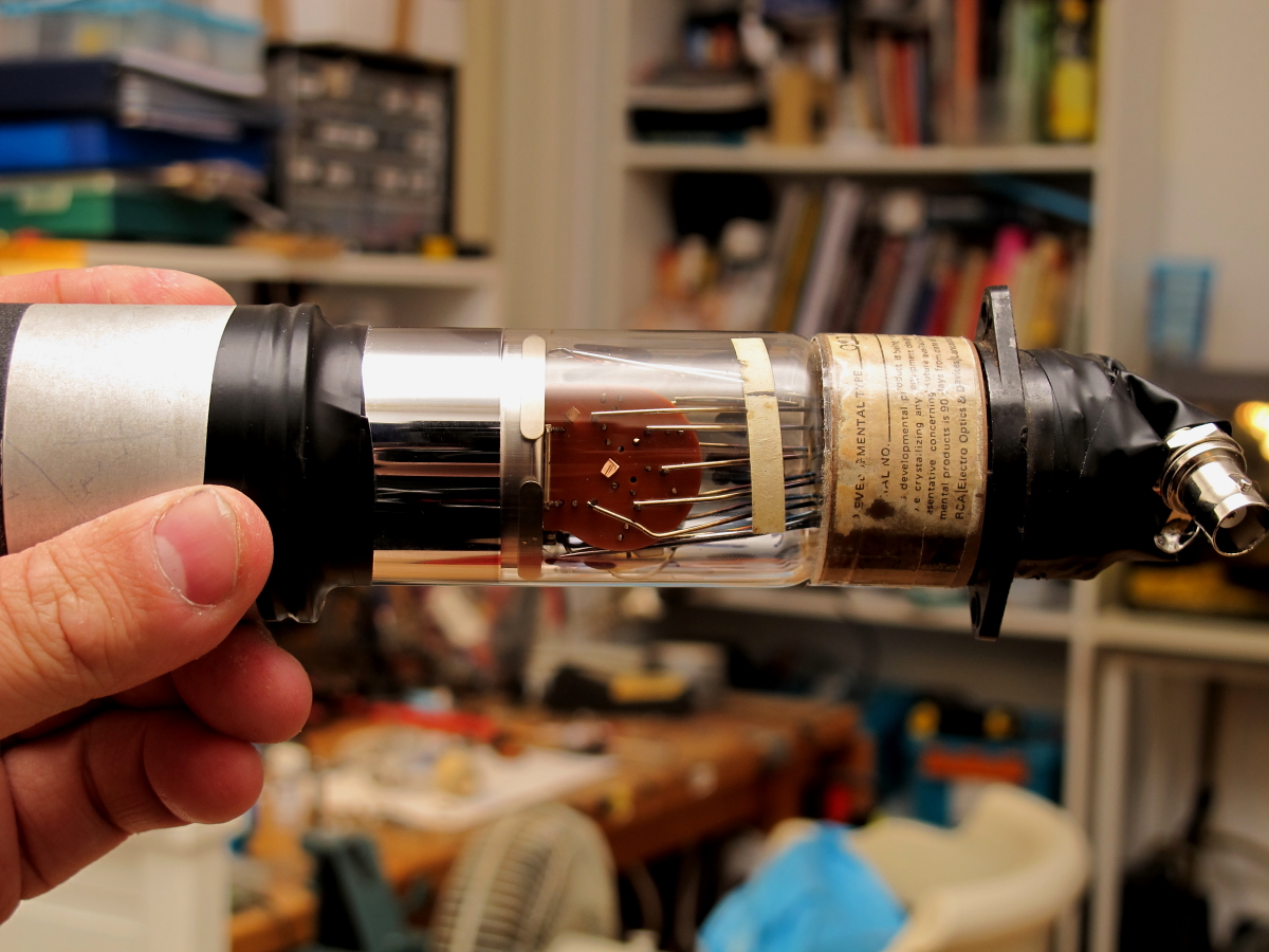
PMTs made for scintillation counting usually have a brown translucent photocathode. If it’s very light brown or seemingly uncolored, usually the tube is defective.
To test working tubes, I have made a special testing box:
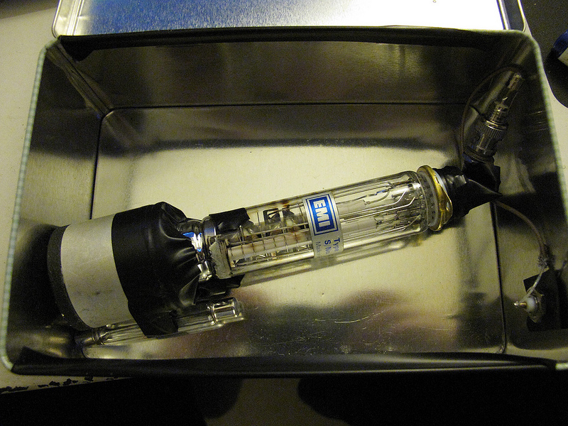
This is a metal box from the discount store. I made a BNC feedthrough to connect the PMT without having to run coax cable between the lid of the box. The box is not completely light tight, but this is easily fixed by putting a little blanket over the box. Shown in the picture are a PMT, my testing crystal and a spark gap containing Cs-137.
Voltage dividers and power supplies
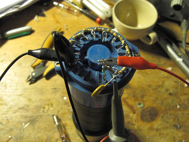
voltage divider testing
PMTs typically run at voltages ranging from a few hundred volts up to 2 kV or more. A lot of PMTs reach their maximum gain at 1500V or less.
To power a PMT, a voltage is applied between the anode, cathode and the dynodes. Using a resistive divider each element has voltage difference of about 100 to 300V relative to its neighbours.
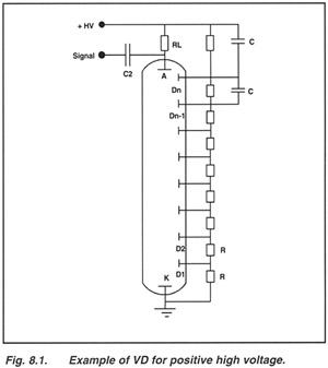
The Dutch company Scionix has a nice page describing voltage divider design. Here is their voltage divider design:
For the counting of pulses I usually use a divider made up of plain 5% 4.7 MOhm resistors. Sometimes the ratio of voltages between the tube elements is not linear, for example certain tubes want a bigger voltage between the cathode and first dynode. For example, the ratio of resistors in the picture above is 2:1:1:1…
To ensure stability at high count rates, capacitors of about 10 nF can be placed between the first/ second and second/third dynode. These can be fairly standard capacitors because they only need to hold off about 300V max between the dynodes.
Total resistance of the voltage divider is dependent on application. For gross counting of gammas high resistances can be used from 30-60 MOhms and up. Lower resistances mean higher count rates as more current is available to the dynodes. Higher resistances result in less current to be available so linearity of pulses for spectrometry might suffer at high count rates.
Scintillation probes usually run on a positive high voltage, which means that the anode receives the high voltage and the cathode is connected to ground. When the PMT sees a light pulse, the current will generate a voltage drop which is coupled to analysing circuitry with a high voltage capacitor.
Portable ratemeters usually require high resistances from 60 MOhms and up. This does not mean spectrometry is not possible, except when high count rates are expected.
Power supply
A PMT usually needs a low current (tens of microamperes) voltage between a couple of hundreds of volts and multiple kilovolts. Most tubes in scintillation probes run at about 1000V.
The supplied voltage needs to be clean, and for spectrometry, really stable. There are some DIY options here, such as:
http://charliethompson.50megs.com/LowRippleHVsupply.html
For superior stability and clean high voltage, there are dedicated PMT power supplies and the so called NIM (Nuclear Instrumentation Module) HV bins, but usually these kind of power supplies are expensive. If you see one for a decent price, get it!
Interfacing
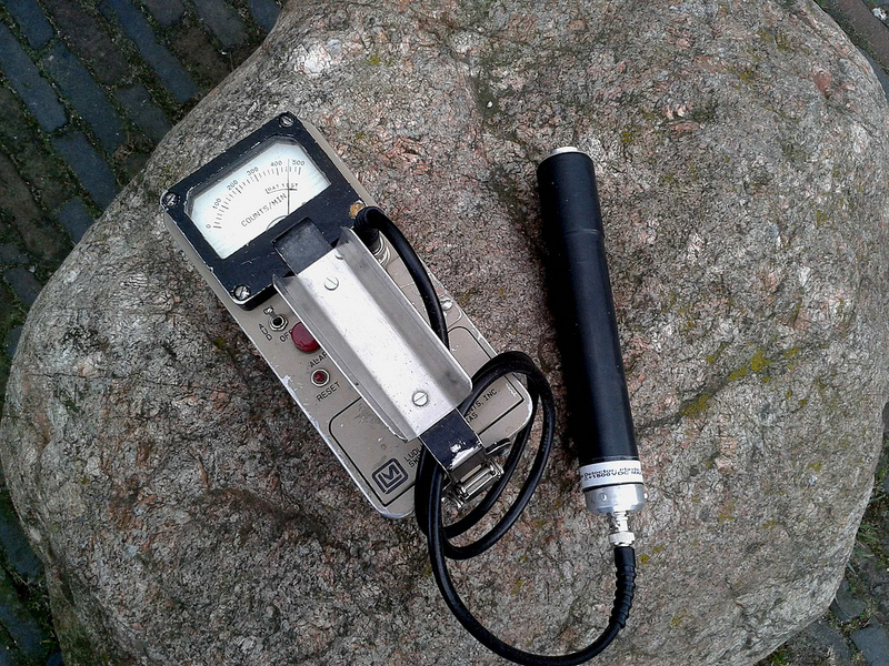 Ludlum model 2A ratemeter with NaI(Tl) probe, detecting gammas in granite
If you only need gross gamma counts, it’s just a case of setting the right high voltage and connecting the probe to a ratemeter. I personally use a Ludlum model 2A that has been modded with an extra range, up to 500K cpm. Scintillation detectors can generate thousands of counts just measuring background radiation, so make sure your ratemeter has the appropriate ranges.
Like GM tubes, scintillation detects have a “plateau” where counts are relatively constant regardless of changes in voltage. When turning up the HV you will at a certain point notice that the counts increase significantly. This is the noise floor of the detection system triggering the threshold of the ratemeter. Just turn down the HV some and you should have proper counts.
My Ludlum model 2A also runs a 44-2 end window tube at 900V and I don’t want to change the HV all the time. The detector shown in the picture runs at about 600-700V. At 900V the signal is too high. Luckily there is a simple fix for this, attenuate the HV by putting a 10M resistor in series with the probe, and place a 3 kV 1 nF capacitor over the resistor to couple the pulses back to the ratemeter/MCA without decreasing their signal level. The actual resistor varies depending on the amount of attenuation desired.
Sound card spectrometry
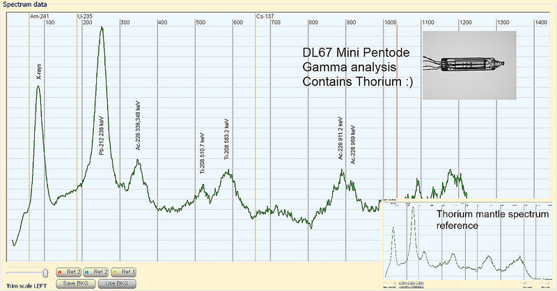 Theremino MCA detecting thorium in a small radio tube
If you have a probe with a scintillator that is suitable for spectrometry such as CsI(Tl), NaI(Tl) or BGO you can analyze the signal with a PC with a sound card. In the past this could only be done using lab-grade dedicated hardware but when people found out that sound cards could do signal acquisition special software was made to perform spectrometry on a PC, software such as PRA and Theremino MCA was created. These software packages record the pulses, reject malformed pulses and can display a graph of all the detected pulse heights, creating a spectrum of the detected gamma energies.
Coupling a PMT to a sound card is rather simple, just feed the pulses into the microphone input of the soundcard. Because the pulses have very quick rise times, they need to be stretched with a RC filter. A simple approach to this is explained here.
There are also complete solutions such as the Gamma Spectacular and the Theremino PMT adapter. These are PMT HV power supplies combined with a sound card interface that run on USB power. With a small laptop you now have a portable gamma spectrometry setup!
Well, this is the end of the article, I hope it provides some information for beginners in radiation detection.
For more information on radiation detection, check out these excellent sources:
Fusor.net Neutron-Radiation detection section
Yahoo! Groups Gammaspectrometry
Yahoo! Groups GeigerCounterEnthousiasts