• Tag Archives Electronica
  • Detecting Radon with an ionization chamber

    Since I am interested in radiation I have been looking into ways of detecting radon and logging the results electronically. There are different ways of detecting radon.There are alpha track detectors which measure radon by having the alpha particles damage plastic and analysing the material later. Lucas cells are used to take an air sample and count the amount of alpha decays detected by a ZnS(Ag) scintillator and a photomultiplier.

    Alpha particles are strongly ionizing due to the fact that they are heavy particles that easily interact with matter. They have enough energy to hit a zinc sulphide scintillator and be visible to a dark-adapted human eye.

    A different way of detecting alpha particles is measuring the amount of ions they generate when they travel through a distance of air. By using an ion chamber, these ions can be converted into a measurable current, and even a discrete current pulse for each alpha ionization event.

    I found Alan Yates’ “Ion Chamber Alpha Particle Counter” to be easy to build. It is a small ion chamber with a JFET and a small circuit using a plain TL072 opamp.

    Some notes for anyone building this circuit:

    • A nice ion chamber can be made using a BNC male to SO-239 adapter and the screw hull from a PL-259 connector. Remove the teflon/plastic from the SO-239 end and solder the source of the JFET to the center pin and the drain to the wall. I covered one end of the screw hull with copper tape and punched a lot of holes in it to allow air to enter the ion chamber
    • Shielding of the JFET is critical, if shielding is insufficient the circuit will detect electric fields from static charges, mains voltage etc. and become unstable.
    • The circuit shows a 2N5484, I used a J201 that I intended to use for another type of alpha detector. I did not need to change the 560 ohm resistor on the source of the JFET.
    • It usually takes a minute for the circuit to settle down. This is because the gate of the JFET is floating and slowly charges up to a stable voltage. Before this happens no proper detections can take place.
    • This is a slow detector, when an alpha particle strikes it takes 100’s of milliseconds for the charge to leak away. During this time no other particles can be detected. In practice this is not a problem since alpha count rates even in high radon environments will not exceed the maximum count rate.

    This circuit is highly recommended for people wanting to research radon. It is easy and cheap to build, does not require high voltages and could be easily adapted to enable logging with microcontrollers. The last thing is a matter of converting the output into a 5/3.3V signal using a voltage divider and connecting it to a microprocessor GPIO pin. I am thinking of using a ESP8266 and ESP Easy’s pulse counting feature to make radon measurements available on the network/internet.

    Here is a video of my build of this circuit in action:


  • Interfacing the Uradmonitor with the Internet of Things, MQTT and Pimatic

    Intro

    For some time I have owned a Uradmonitor model A unit. This is a radiation monitoring solution which measures radiation and makes it available on a website. Connect it to your local network, and it will automatically get an IP address and start logging to www.uradmonitor.com. There you can find the stations and associated readings on a map.

    Since the Uradmonitor has a webinterface it is easy to scrape the data and send it elsewhere. For example, the CPM can be displayed on a VFD display or displayed in domotics applications.

    At home I try to make any sensor reading available using Mosquitto/MQTT. It is a lightweight, easy to use protocol to distribute dynamic data. Besides the Uradmonitor, multiple NodeMCU ESP8266 units running ESP Easy publish their sensor readings to the local MQTT server. All of this is done by Mosquitto running on my Debian ARM NAS and a Raspberry Pi running Raspbian and Pimatic.

    Scraping and publishing to MQTT

    First off I scrape the data from the Uradmonitor webpage using curl. Then, after some awk and html2text processing it is published to my local MQTT server using the mosquitto_pub MQTT publishing client.

    #!/bin/bash
    uradmonitorcpm=$(curl -s http://<ip of uradmonitor/ | html2text | grep radiation | egrep -o '[0-9.]*')
    mosquitto_pub -m $uradmonitorcpm -t /uradmonitor/cpm

    This bash script runs every minute using /etc/crontab and updates the local MQTT server with the latest measurement. The command ends with the MQTT topic which is the “address” of the dynamic value on the MQTT server.  Please note that mosquitto_sub does not need an IP address when publishing to localhost/127.0.0.1 since that is a default of the client. To specify a host, use the -h <ip address of mqtt server> option. Continue reading  Post ID 3618


  • Trinket powered geiger counter

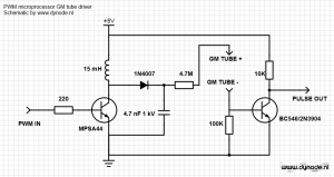
    Lately I have been messing around a bit with microprocessor powered geiger counters. One smart guy came up with the idea of generating high voltage using PWM signals from the microprocessor itself. With some additional external parts a HV supply and negative going pulse suitable for microprocessors is easy to make. Here is a schematic I came up with:

    gm counter interface

    The circuit works as follows: A ~1 Khz squarewave turns the MPSA44 high voltage transistor on and off, generating high voltage when the  inductors current is shut off. The voltage depends on the pulse width of the square wave which can be tweaked in software. The 1N4007 diode rectifies this voltage, and the HV cap removes most of the ripple on this voltage. The resistor limits current to the GM tube. The current pulses from the tube generate a voltage drop over the 100K resistor which turns on the BC546. When this happens the voltage through the 10K resistor is pulled to ground, generating a negative going pulse each time the GM tube detects an ionizing ray or particle.

    To drive this circuit I used my new Adafruit Trinket, a small board with a Attiny85 microprocessor. Using the tutorials on the Adafruit website it is easy to work with from the Arduino environment. Here is the code:

    void setup() {
     analogWrite(0, 30); //starts PWM on pin 0, generates about 400V
     analogWrite(1, 255); // needed to get LED to full brightness
     attachInterrupt(0,countPulse,FALLING); // attach interrupt to pin 2
     }
    void loop() {
     //nothing much really
     }
    void countPulse(){
     //pulse led
     digitalWrite(1, HIGH);
     delay(100);
     digitalWrite(1,LOW);
     }

    And here is a video of the setup in use:


    Of course it is rather wasteful to only use the microprocessor to generate PWM and flash a LED. I plan on implementing counting and serial output in software later. Unfortunately the Trinket does not have native serial USB capability but bit banging a serial signal on one of the pins should work fine according to several sites. Then it is just a matter of adding a cheap PL2303 serial to USB adapter.

    Update 18/4/2014

    Added serial logging capability. Using a tx only software serial library, the Trinket outputs the measurements in CPM each 10 seconds on pin 4. New code:

    // Trinket GM counter by Johan/dynode.nl
    
    //counting vars
    long count = 0;
    long countPerMinute = 0;
    
    // init softserial only tx on pin 4
    #include <SendOnlySoftwareSerial.h>
    SendOnlySoftwareSerial mySerial (4);
    
    void setup() {
      mySerial.begin(9600); // init serial 9k6
      analogWrite(0, 30); //starts PWM on pin 0, generates about 400V
      analogWrite(1, 255); // needed to get LED to full brightness
      attachInterrupt(0,countPulse,FALLING); // attach interrupt to pin 2
      mySerial.println ("Trinket GM counter starting..."); 
    }
    
    void loop() {
      delay(10000); //the count is incrementing during this delay
      countPerMinute = 6 *count;
      mySerial.println (countPerMinute);
      count=0; //reset the count
    }
    
    void countPulse(){
        count++;
        //pulse led when count is increased
        digitalWrite(1, HIGH);
        delay(100);
        digitalWrite(1,LOW);
      }

    Example serial output using cheap eBay USB<>TTL serial adapter:

    Trinket GM counter starting...
    84
    12
    6
    0
    402        <--- thorium bearing mantle held next to GM tube
    996
    1218
    1146
    1074
    1104


    There still need to be some tweaking done, the circuit is quite susceptible to electromagnetic interference which causes erroneous counts.


  • PMTs and scintillation probes

    quickprobe

    temporary probe with NaI(Tl) crystal, PMT, socket with voltage divider and BNC socket

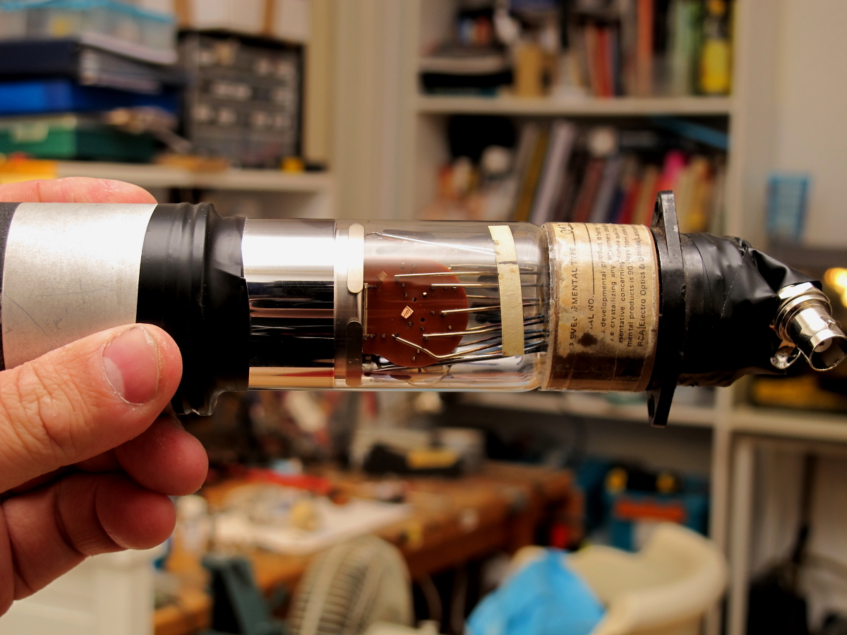
    Following is a little guide to using photomultiplier tubes in DIY scintillation probes.

    Photomultipliers are vacuum tubes that convert light into electrons and multiply the resulting current up to millions of times. They are used to detect the minute flashes of light generated by scintillators, materials that convert gamma and x-rays into visible light.

    How to use these tubes? There are some things you need to remember when working with PMTs.

    Continue reading  Post ID 3618


  • Raspberry Pi remote sensors

    Posted on by Johan

    I recently bought a Raspberry Pi to experiment with. The first things I did with it was connecting and reading out Maxim Integrated DS1820 one wire temperature sensor and the cheap Chinese DHT11 temperature / relative humidity sensor.

    To connect the sensors, I soldered some female pin headers to a piece of PCB. For the one wire network I soldered a 4.7K resistor between Vcc on pin1 (3.3V) and GPIO4 on pin 7. GPIO4 is the data pin for one wire, I used GPIO2 as the data pin for the DHT11.  DHT11 “modules” with a PCB and three pins have their own pull up resistor, the separate 4 pin sensors don’t. Shown below is the quick setup, I soldered the DS1820 directly to the PCB, and connected the DHT11 with some wires for 3.3V, data and ground.

    rasp_gpio_ds1820_dht11


    GPIO pinouts differ between the Raspberry Pi versions, I found the following pinout to be correct for my Raspberry Pi, a model A version 2.

    Reading out the sensors is easy. For the DS1820, load the required kernel modules which are included in the Raspbian Linux distribution: Continue reading  Post ID 3618